LANGUAGE

 Español
 عربى
عربى
Xinhong Valve & Fitting
Xinhong Valve & Fitting
Xinhong Valve & Fitting
Xinhong Valve & Fitting
Xinhong Valve & Fitting
Xinhong Valve & Fitting
Xinhong Valve & Fitting
Xinhong Valve & Fitting
Xinhong Valve & Fitting
Xinhong Valve & Fitting
Xinhong Valve & Fitting
Xinhong Valve & Fitting
Xinhong Valve & Fitting
Xinhong Valve & Fitting
Xinhong Valve & Fitting
Xinhong Valve & Fitting
When it comes to flow control, there's one name that keeps popping up: Globe valve. Whether you’re in the oil and gas industry, managing a water treatment plant, or just working in a power station, chances are you've come across one. But what makes globe valves such a reliable option?
What's a Globe Valve, Anyway?
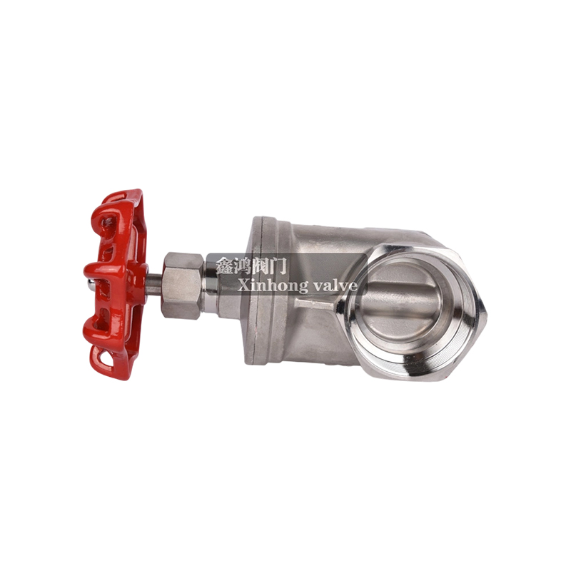
Think of a globe valve like a faucet with extra control. It’s designed to start, stop, and regulate the flow of fluid—usually water, gas, or steam—through a pipeline. The name "globe" comes from its body shape, which kind of looks like a round globe. Inside, there’s a movable disk-type element and a stationary ring seat in a generally spherical body. That setup gives you precise control.
Why Do People Still Use Globe Valves?
In a world full of high-tech, automated options, the fact that globe valves are still going strong says something. Here's why engineers and technicians still love them:
Great flow control: Compared to other valves like gate or ball valves, globe valves give you much finer control.
Tight shut-off: They seal well, so there’s less risk of leaks when the valve is closed.
Durable: Built to last under high-pressure and temperature conditions.
Easy to maintain: Many designs make it simple to replace parts without removing the whole valve.
Where Do You See Globe Valves?
Globe valves are everywhere. You’ll find them in:
- HVAC systems
- Power plants
- Chemical processing facilities
- Oil and gas pipelines
- Water and wastewater treatment
They’re especially handy where flow needs to be throttled or adjusted regularly. If you need reliable, precise flow control, the globe valve is still one of the best tools for the job. It may not be the flashiest part of your system, but it gets the job done—and keeps doing it for years. Whether you're an engineer designing a new plant or a technician maintaining existing infrastructure, don’t overlook the globe valve. It’s a classic for a reason.
The Distinction and Application of Industrial and Control Globe Valves
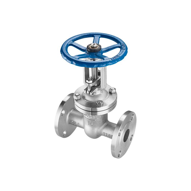
In the precise orchestration of industrial fluid systems, the regulation of flow, pressure, and temperature is fundamental to safety, efficiency, and product quality. While many valve types exist for on/off isolation, the need for accurate modulation requires a different design philosophy. Globe valves, characterized by their spherical body shape and a plug-style disc that moves perpendicularly to a stationary ring seat, are engineered for this very purpose. Their linear motion design provides a stable, controllable relationship between stem position and flow area, making them the foundation for both manual regulation and automated process control.
Industrial Globe Valves: Design and Function
Industrial globe valves are manually or gear-operated valves primarily designed for throttling flow and providing reliable shut-off in applications where such regulation is frequently required. Their internal geometry creates a more tortuous flow path compared to gate or ball valves, resulting in a higher inherent pressure drop, which is a deliberate trade-off for controllability. The key components include a rising stem, a handwheel or actuator connection, a disc (or plug), and a seat ring, usually arranged such that the flow enters below the seat and exits above it. They are distinguished from simple on/off valves by their suitability for frequent adjustment and their ability to withstand the erosive forces of partially open positions better than alternatives. The following table outlines their primary characteristics, common designs, and typical applications.
|
Characteristic |
Description |
Typical Industrial Application |
|
Primary Function |
Precise manual throttling (flow regulation) and shut-off. |
Regulating coolant flow to a heat exchanger, adjusting feed rates in batch processes, isolating sections for maintenance. |
|
Common Body Patterns |
Standard (T-Pattern): Many common, high pressure drop. Angle Pattern: Changes flow direction 90°, reduces erosion. Y-Pattern: Straight-through flow, lower pressure drop for throttling. |
T-Pattern: General service. Angle Pattern: Boiler blowdown, frequent cycling. Y-Pattern: High-pressure steam, oil, and gas lines. |
|
Disc & Seat Design |
Plug Disc: For fine throttling. Composition Disc: (e.g., resilient insert) for bubble-tight shut-off. Metal Seats: For high temperatures. |
Plug/Metal: Steam service, high-temperature hydrocarbons. Composition: Water, air, lower temperature services requiring tight seal. |
|
Flow Direction |
Typically, flow enters under the seat and exits above it. This pressure assists in closing and prevents stem packing load in shut-off. |
Critical for installation; reverse flow can cause instability and difficulty in opening against pressure. |
|
Materials of Construction |
Cast or forged carbon steel, stainless steel, alloy steels, bronze. Chosen for pressure, temperature, and fluid compatibility. |
Carbon Steel: Steam, water, oil. Stainless Steel: Corrosive chemicals, food, marine. Alloy Steels: High-temperature power generation. |
Globe Control Valves: Automated Process Modulation
Globe control valves are a specialized subset of globe valves designed not for manual operation, but for automated, precise modulation of a process variable (like flow, pressure, or level). They are the final control element in a loop, receiving a signal from a controller to position their stem accurately.
What is the fundamental difference between a manual globe valve and a globe control valve?
The core difference lies in design intent and precision. A manual industrial globe valve is built for durability and reliable shut-off with occasional or regular manual adjustment. A globe control valve is engineered for continuous, precise, and often rapid automatic modulation. It features a characterized plug (e.g., equal percentage, linear, quick opening) tailored to the process dynamics, a high-precision actuator (pneumatic, electric, hydraulic), and often a positioner to ensure the stem moves to the exact position commanded by the control signal, compensating for friction and system pressure changes.
What are common trim types and why are they selected?
"Trim" refers to the internal, wetted parts that modulate flow: the plug and seat. Contoured Plugs are shaped to provide a specific flow characteristic (linear, equal percentage). Cage-Guided Trim uses a perforated cage to stabilize the plug, reduce vibration, and enable easy trim changes for different capacities or materials. Cavity Control Trim is designed to minimize noise and cavitation. The selection is based on required flow characteristic, pressure drop, fluid properties, and the need for reduced noise or anti-cavitation performance.
How does an actuator and positioner work with the valve?
The actuator is the muscle. A common type is a pneumatic diaphragm actuator, where air pressure moves a diaphragm connected to the stem. The positioner is the brain. It receives a 4-20 mA or 3-15 psi signal from the process controller, compares it to the actual stem position via a feedback link, and adjusts the air supply to the actuator until the stem is at the precisely correct position. This closed-loop control within the valve assembly is key to accurate process automation.
Where are globe control valves typically used?
Their precision makes them ubiquitous in continuous process industries. They control fuel flow to furnaces, regulate reactant feed in chemical plants, maintain precise pressure in distillation columns, manage coolant flow for temperature control in refineries, and modulate steam for turbine speed control in power plants. Essentially, they are used wherever a process variable must be maintained automatically at a specific setpoint.
While sharing a common ancestry in linear motion design, industrial globe valves and globe control valves serve distinct purposes. The industrial variant is a robust, manually adjusted workhorse for regulated flow, while the control valve is a sophisticated, automated instrument for precise process modulation.