LANGUAGE

 Español
 عربى
عربى
Xinhong Valve & Fitting
Xinhong Valve & Fitting
Xinhong Valve & Fitting
Xinhong Valve & Fitting
Xinhong Valve & Fitting
Xinhong Valve & Fitting
Xinhong Valve & Fitting
Xinhong Valve & Fitting
Xinhong Valve & Fitting
Xinhong Valve & Fitting
Xinhong Valve & Fitting
Xinhong Valve & Fitting
Xinhong Valve & Fitting
Xinhong Valve & Fitting
Xinhong Valve & Fitting
Xinhong Valve & Fitting
The manual socket welding threaded ball valve has emerged as a preferred flow control component for medium-pressure piping systems in chemical processing, water treatment, and industrial utility networks. This valve design combines a socket welding end connection on one side with a threaded end on the other, allowing installers to join pipe sections using either method depending on site access and existing fitting types. Recent installation records indicate that these hybrid-end valves reduce total joint count in compact piping layouts, while the manual lever operation provides simple, visual position indication without requiring power sources or complex actuation systems.
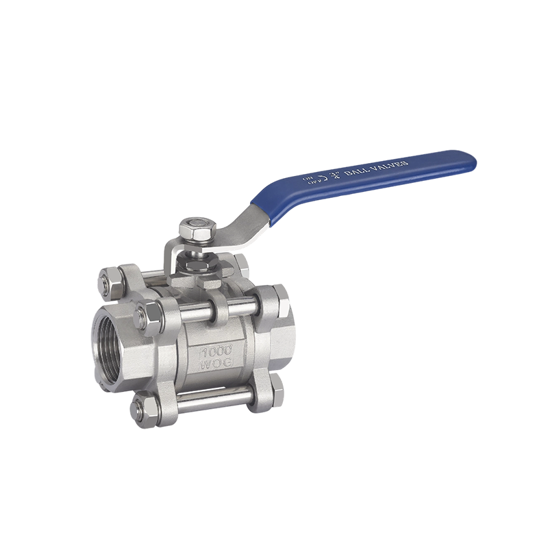
Design Configuration and End Connection Options
The manual socket welding threaded ball valve features a one-piece or two-piece body construction, typically forged from carbon steel or stainless steel grades that match common pipeline materials. The socket welding end accepts pipe insertion into a recessed socket, followed by fillet welding around the joint circumference, creating a permanent, leak-tight connection that withstands vibration and thermal cycling. The threaded end, usually cut to national pipe thread or British standard pipe thread specifications, enables screw-on attachment to existing female-threaded fittings, unions, or equipment ports. This dual-connection design gives engineers flexibility in retrofit projects, where one side of the valve must mate with welded pipe runs while the other ties into threaded branch lines or replaceable components. Common sizes range from 1/2 inch to 2 inches, with pressure ratings up to 1000 psi depending on material and temperature derating factors.
Ball and Seat Sealing Mechanism
Inside the valve, a chrome-plated or stainless steel ball with a cylindrical through-bore rotates between two polymeric seats, typically made from reinforced polytetrafluoroethylene or modified polyamide materials. When the handle is turned 90 degrees from the closed position, the ball's bore aligns with the pipe axis, allowing full-port flow with small pressure drop. Key sealing features that contribute to reliable shutoff include:
Spring-energized seat rings that maintain contact pressure against the ball surface even after thermal expansion or contraction cycles;
- Precision-ground ball spheres with surface roughness ratings below 0.4 micrometers, ensuring smooth rotation and low operating torque;
- Stem seals composed of multiple V-ring stacks or O-rings that prevent fugitive emissions around the handle shaft;
- Blowout-proof stem design that retains the shaft even if internal pressure forces the stem upward during operation;
- Cavity-fill geometry that less dead space where process fluids can stagnate or crystallize.
These sealing elements are validated through hydrostatic and pneumatic seat leakage tests, with acceptable rates typically below 0.1 percent of rated flow capacity.
Manual Lever Operation and Position Indication
The manual socket welding threaded ball valve uses a lever-type handle that provides clear visual feedback of valve position. When the handle is parallel to the pipe axis, the valve is open; when perpendicular, it is closed. This intuitive orientation reduces operator error during shift changes or emergency responses, as the open/closed status can be assessed from a distance without removing insulation or climbing to elevated platforms. The lever is typically fabricated from stamped steel or cast zinc alloy, with a vinyl or nylon grip that improves handling comfort and insulates against temperature bad. Some versions incorporate a locking mechanism—either a padlock hasp or a spring-loaded detent—that secures the handle in either fully open or fully closed positions, preventing unauthorized or accidental operation in critical service lines. Operating torque ranges from 5 to 30 newton-meters depending on valve size and pressure class, with smooth action maintained by periodic lubrication of the stem-bearing interface.
Installation Practices for Socket Weld and Threaded Joints
Proper installation of the manual socket welding threaded ball valve requires attention to both connection types to avoid stress-induced leakage or distortion. For the socket welding side, fit-up clearance between the pipe outer diameter and socket inner diameter should follow standard tolerances, typically 0.1 to 0.2 millimeters, allowing capillary action to draw filler metal during welding. Welders apply a single-pass fillet weld around the entire circumference, with interpass temperature control to prevent carbide precipitation in stainless steel grades. For the threaded side, installers use thread sealants or PTFE tape applied in the direction of thread rotation, with torque values calibrated to the valve material and pipe schedule. Recommended practices during installation include:
- Supporting the valve body with a backup wrench to prevent twisting forces from damaging internal seats;
- Avoiding over-torquing on the threaded connection, which can distort the body and affect ball-seat compression;
- Performing a partial open-close cycle after installation to verify smooth operation without binding;
- Pressure-testing the assembled joint at 1.5 times the big working pressure before commissioning.
Application Suitability and Fluid Compatibility
The manual socket welding threaded ball valve handles a broad spectrum of fluids, including water, air, natural gas, light oils, and mild chemical solutions, provided that material selections align with service conditions. Carbon steel bodies with zinc-plated or epoxy-coated exteriors suit non-corrosive or slightly corrosive environments, while 316 stainless steel versions resist chloride attack and acidic media. For high-temperature applications above 200°C, graphite-packed stem seals and metal-seated ball designs are available, though these variants require higher operating torque and more frequent maintenance. The valve's compact dimensions—typically two to three times the pipe diameter in overall length—allow installation in confined spaces where flange-type valves would not fit. Common installation points include pump discharge lines, tank bottom outlets, instrument isolation branches, and equipment drain connections.
Maintenance and Overhaul Procedures
Routine maintenance of the manual socket welding threaded ball valve focuses on stem seal integrity, handle tightness, and seat wear condition. Operators check for external leakage by applying soap solution around the stem and end connections during pressurization, with any bubbles indicating seal degradation. For valves that cycle frequently—more than 500 operations per year—manufacturers recommend annual stem seal replacement and seat inspection. Overhaul steps include:
- Depressurizing and isolating the valve section before any disassembly;
- Removing the handle, stem nut, and stem assembly to access the ball and seats;
- Inspecting the ball surface for scoring, pitting, or loss of chrome plating;
- Measuring seat ring thickness and replacing if worn below the small specification;
- Cleaning all internal surfaces with compatible solvents and reassembling with fresh lubricant.
After reassembly, technicians perform a leak test at operating pressure, cycling the valve several times to distribute fresh seal lubricant evenly.
Reputable manufacturers also provide stem torque data and cycle-life projections based on type-testing protocols, giving end users confidence in the valve's long-term reliability. With proper selection, installation, and maintenance, the manual socket welding threaded ball valve delivers dependable isolation and flow control for decades of industrial service.