LANGUAGE

 Español
 عربى
عربى
Xinhong Valve & Fitting
Xinhong Valve & Fitting
Xinhong Valve & Fitting
Xinhong Valve & Fitting
Xinhong Valve & Fitting
Xinhong Valve & Fitting
Xinhong Valve & Fitting
Xinhong Valve & Fitting
Xinhong Valve & Fitting
Xinhong Valve & Fitting
Xinhong Valve & Fitting
Xinhong Valve & Fitting
Xinhong Valve & Fitting
Xinhong Valve & Fitting
Xinhong Valve & Fitting
Xinhong Valve & Fitting
The three-dimensional check valve has become a preferred flow control component for piping systems requiring reliable backflow prevention in multi-directional layouts. Unlike conventional swing or lift check valves that operate along a single axis, this valve employs a spring-loaded disc mechanism that responds to pressure differentials from multiple approach angles, making it suitable for complex manifold arrangements and equipment skids. Recent installation data indicate that these valves reduce pressure drop compared to traditional designs, while their compact body dimensions allow mounting in tight spaces where standard check valves would not fit.
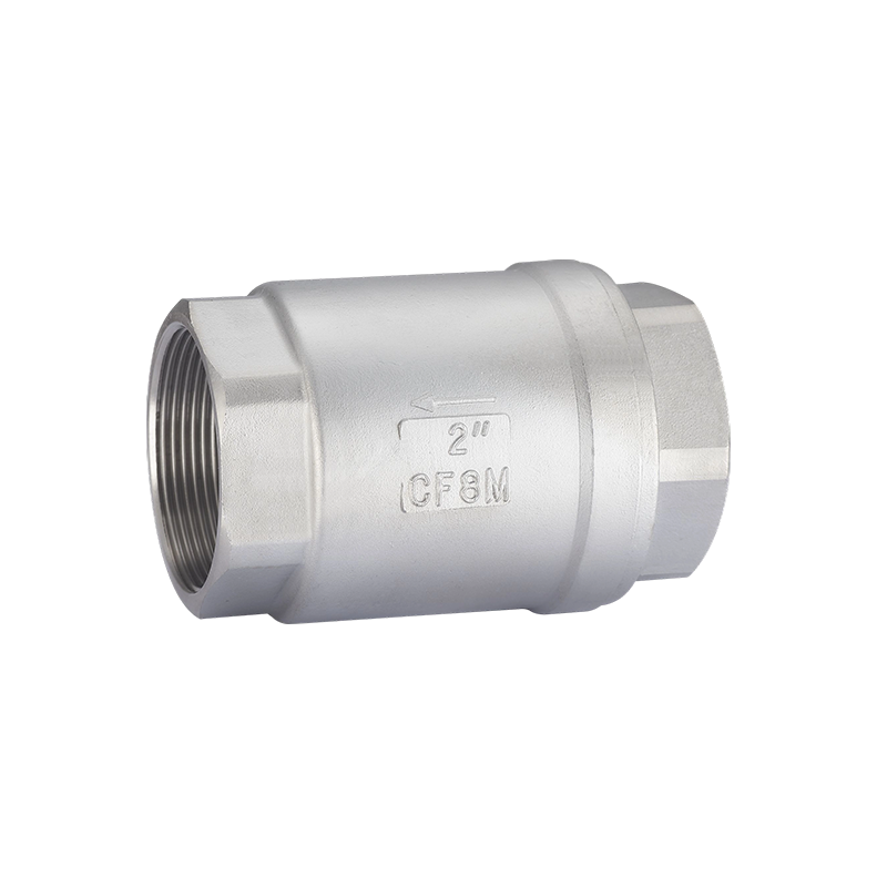
Valve Construction and Operating Principle
The three-dimensional check valve features a body with inlet and outlet ports oriented at various angles, typically 90 or 180 degrees apart, with the internal disc assembly moving perpendicular to the flow path. The disc is guided by a stem or cage that maintains alignment during opening and closing strokes. A compression spring holds the disc against the seat when upstream pressure falls below the cracking threshold. When forward flow begins, pressure forces the disc off the seat, allowing fluid passage through the valve. When flow stops or reverses, the spring and back pressure return the disc to the closed position. Key construction details include guided disc designs that prevent tilting, spring materials selected for the service temperature range, and seat materials matched to fluid compatibility requirements.
Check Valve Configurations and Body Styles
The three-dimensional check valve is available in multiple body configurations to suit different piping arrangements. Wafer-style bodies fit between flanges with through-bolts, offering the shortest face-to-face dimensions. Lug-style bodies feature threaded inserts for bolting to one flange, allowing blind-end mounting. Flanged bodies provide standard bolted connections for larger line sizes. The disc and seat assemblies are designed for in-line serviceability, with some models featuring top-entry bonnets that allow internal inspection without removing the valve from the pipeline. Special configurations include soft-seat versions for low-pressure drop applications and metal-seated designs for high-temperature or abrasive services.
Cracking Pressure and Flow Characteristics
The cracking pressure of the three-dimensional check valve is determined by the spring rate and disc weight, typically set between 0.1 and 0.5 bar for standard water services. Higher cracking pressures are available for vertical installations where gravity must be overcome. The flow coefficient varies with line size and body style, with full-port designs offering the low pressure drop. Opening characteristics include rapid lift under increasing flow, with the disc reaching full travel at approximately 1.5 times the cracking pressure. This responsive opening prevents chatter, a common issue in swing check valves at low flow conditions. The design also accommodates pulsating flow from reciprocating pumps, with spring dampening that stabilizes disc position during pressure fluctuations.
Installation Orientation and Location Guidelines
The three-dimensional check valve can be installed in horizontal, vertical upward, or vertical downward flow orientations, depending on the specific model's spring configuration. Key installation considerations include:
- Flow arrow direction must match the actual flow path, as reverse installation prevents opening;
- Upstream straight pipe runs of at least five diameters to avoid flow disturbances that affect disc stability;
- Downstream clearance for disc movement, as the disc protrudes into the downstream cavity during full opening;
- Access space for maintenance, particularly for top-entry designs requiring bonnet removal.
For vertical downward flow installations, spring-assisted models are recommended to ensure positive closing against gravity. Multiple valve installations on parallel lines should maintain consistent orientation across all units.
Spring Selection and Temperature Effects
The spring material directly influences the valve's performance across temperature bad. Stainless steel springs suit most water and light chemical services up to 200°C. Inconel or Hastelloy springs are required for high-temperature applications above 300°C or for corrosive media. Spring preload is factory-set to the specified cracking pressure; field adjustments are not recommended as they can alter disc travel and seating characteristics. At elevated temperatures, spring force decreases due to modulus reduction, potentially lowering the cracking pressure. At low temperatures, springs stiffen, increasing the required opening force. These effects are accounted for in the valve's pressure-temperature rating tables, with derating factors applied for bad conditions.
Flow Cavitation and Noise Considerations
In high-pressure drop applications, the three-dimensional check valve can experience cavitation when the downstream pressure falls below the fluid's vapor pressure. Cavitation damage appears as pitting on the disc and seat surfaces, gradually increasing leakage and reducing service life. To mitigate this, users select valves with hardened trim materials or install the valve with adequate back pressure to prevent flashing. Noise generated by high-velocity flow through the valve is typically lower than swing checks due to the guided disc design, but silencers or acoustic insulation may be required for sensitive environments. For critical applications, manufacturers offer anti-cavitation trims that stage the pressure drop through multiple throttling surfaces.
Maintenance and Service Intervals
Routine maintenance for the three-dimensional check valve includes inspection of the disc, seat, spring, and guiding surfaces. Recommended service intervals depend on service severity, with general water applications checked annually and severe services every three to six months. Maintenance steps include:
- Removing the valve from the line and disassembling according to manufacturer instructions;
- Inspecting the disc and seat for wear, erosion, or corrosion damage;
- Checking the spring for deformation, breakage, or loss of preload;
- Reassembling with fresh lubrication on guiding surfaces and replacing any worn components.
After reassembly, technicians verify that the disc moves freely through its full travel and that the spring returns the disc to the seat without binding. Pressure testing at 1.1 times the cracking pressure confirms leak-tight closure.
Material Selection and Fluid Compatibility
Body materials range from cast iron and ductile iron for water services to carbon steel for oil and gas applications, and stainless steel for corrosive fluids. Seat materials include nitrile, EPDM, and PTFE for soft-seat designs, and 13 percent chromium steel, stainless steel, or stellite for metal-seated versions. When selecting materials, engineers consider temperature, pressure, fluid corrosivity, and abrasiveness. For seawater services, bronze or super duplex stainless is preferred. For high-purity applications such as pharmaceuticals, electropolished stainless steel with PTFE seats less contamination risk. Each combination is verified against industry standards such as API 594 or ASME B16.34.
Application Sectors and Typical Uses
The three-dimensional check valve serves multiple industries including water and wastewater treatment, where they prevent backflow in pump discharge lines and lift stations. In HVAC systems, they protect chillers and cooling towers from reverse flow during pump shutdown. The petrochemical sector uses them in loading racks, tank farms, and process unit feed lines. Power plants install them on cooling water circuits, steam drains, and auxiliary systems. The compact design and reliable operation have made them a common choice for modular skid assemblies, where space limitations and multi-directional piping create demands that traditional check valves cannot easily meet.