LANGUAGE

 Español
 عربى
عربى
Xinhong Valve & Fitting
Xinhong Valve & Fitting
Xinhong Valve & Fitting
Xinhong Valve & Fitting
Xinhong Valve & Fitting
Xinhong Valve & Fitting
Xinhong Valve & Fitting
Xinhong Valve & Fitting
Xinhong Valve & Fitting
Xinhong Valve & Fitting
Xinhong Valve & Fitting
Xinhong Valve & Fitting
Xinhong Valve & Fitting
Xinhong Valve & Fitting
Xinhong Valve & Fitting
Xinhong Valve & Fitting
A 3 Port Ball Valve plays a critical role in systems that require controlled redirection or a combination of fluid flow. Understanding how this valve operates internally helps operators avoid incorrect usage and improve system coordination. Proper knowledge of flow path control is especially important in complex piping layouts where multiple routes exist, as even minor misoperation can lead to pressure fluctuations, media waste, or even system downtime.
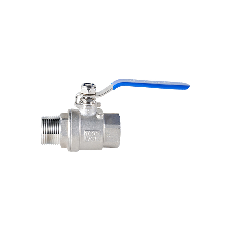
Basic Structure of a 3 Port Ball Valve
The valve consists of a body with three ports, a rotating ball with internal passages, sealing components, and an operating mechanism. The internal ball is drilled or shaped to create specific flow paths—common designs include L-shaped and T-shaped passages, each tailored to distinct flow control needs. By rotating the ball (typically 90 degrees for full position switching), the valve connects or blocks different ports to achieve the desired flow routing. The sealing elements, often made of PTFE, rubber, or metal, depending on the media temperature and corrosiveness, ensure tight closure while allowing smooth rotation. Proper alignment between the ball and valve body is essential for correct operation, as misalignment can cause leakage or increased operating torque.
How Ball Rotation Controls Flow Direction
Flow control is achieved by rotating the ball inside the valve body. Each rotation position aligns the internal passage with different ports; for example, a 0-degree position might connect Port 1 to Port 2, while a 90-degree rotation switches the connection to Port 1 and Port 3. This alignment determines which ports are connected and which are isolated. Clear identification of handle position or actuator orientation (such as marked "Open/Close" indicators or position sensors for automated valves) helps operators understand current flow status. Misinterpretation of these positions can lead to unintended flow routing, which is particularly hazardous in chemical processing or high-pressure systems.
Flow Control in L-Port Valves
L-port designs allow flow to move between two selected ports at a time, with the third port always isolated. This design is commonly used in switching applications where one inlet supplies multiple outlets in alternating cycles, such as in heat exchanger systems where a heating or cooling medium is switched between two circuits. Proper installation orientation is important—for instance, the inlet port should align with the straight end of the L-shaped passage to ensure unobstructed flow. Incorrect alignment may result in blocked flow or unexpected isolation of certain lines, disrupting the entire system’s operation.
Flow Control in T-Port Valves
T-port designs allow multiple flow combinations: one inlet to two outlets, two inlets to one outlet, or even mixing of two media streams in the T-shaped passage. They are often used in mixing applications (e.g., blending two chemical components at a controlled ratio) or systems where simultaneous distribution is required, such as distributing a cooling fluid to multiple equipment units. Operators should be aware that not all positions fully isolate flow—for example, some intermediate rotation positions may leave all three ports partially connected. Understanding the internal passage layout through valve manuals or cross-sectional diagrams helps prevent confusion during operation.
Practical Flow Path Control Tips
Before installation, reviewing flow diagrams is essential to confirm that the valve’s port configuration matches the system’s flow requirements. Marking port functions (e.g., "Inlet," "Outlet 1," "Outlet 2") and handling positions directly on the valve body or adjacent piping helps avoid operational errors, especially during shift changes or maintenance. During maintenance, checking internal alignment (using calibration tools if necessary) and inspecting sealing components for wear ensures continued reliability. Additionally, for automated 3 Port Ball Valves, regular testing of actuator response and position feedback systems is crucial to maintain precise flow control.
Clear labeling and documentation reduce the risk of incorrect valve operation in complex systems.
Understanding the working principle of a 3 Port Ball Valve improves flow management and reduces operational risks. Proper flow path control depends on correct installation, clear orientation, and awareness of internal valve design.